- Out-of-Stock
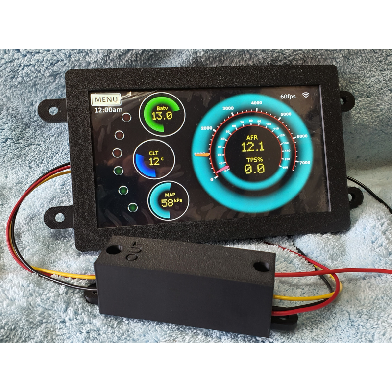


SDC Pro 7 is our latest pre-built SDC product.
SDC Pro 7 is fully customisable with whatever screen graphics, gauges, and boot graphics you prefer, using any of the SDC capabilities as described on the SDC software help pages. It comes fitted inside a housing containing 4 mounting lugs with 6mm holes so that you can mount through a hole in your dashboard.
SDC Pro 7 is very easy to connect to your ECU. All you need is 3 wires for power and switched power, and a connection to your ECU - either Serial (3 wires) or CANBus (2 wires).
** See separate notes in the description section on CANBus support **
Specifications:
* 7" HDMI Capacitive touch monitor; 1024x600 resolution
* Raspberry Pi 3A+ embedded behind the screen.
* Controlled shutdown module in a separate case with mounting lugs, with a 5 second delay.
* Latest SDC I/O Hat with power supply, Serial interface input, CANBus I/O, and ignition trigger input.
* 255 Page SDC License (i.e. all pages) with 'extras' enabled for future expansion.
* 32Gb SD Card with licensed SDC installed.
This product is pre-assembled and ready to be wired directly to your Speeduino ECU.
The screen in this kit has 10 levels of brightness which you can cycle through using the SDC PULSEGPIO touch action. The demo pageset it boots with contains a menu with this action enabled to demonstrate how it works. The chosen brightness is remembered by the display next time it is powered on.
The single USB port on this device is used by the touchscreen.
For getting started instructions, see the Pro7 Product instructions in https://sdc.v8creations.com//products/products.html
Please note the screen in the images still has the protective film on it, in case you are wondering what the wrinkles are on the screen.
The SDC installation on the device will be functional and configured in Demo (playback) mode. You will need to configure it for your WIFI network, switch it to a relevant input/output mode such as Serial or CANBus, and design screens for whatever purpose you need. See the SDC Help Pages for information on how to do this.
* Width excluding mounting lugs 184mm
* Height excluding mounting lugs 116mm
* Lug Size 20mmx15mm with 6mm hole
* Distance from face of lug to face of bezel 15mm i.e. bezel thickness
* Total depth including the hardware mounted on the rear 43mm
The width and height represent the size of the hole required for the bezel to fit through.
The distance from face of lug to face of bezel represents how far the bezel will protrude through an opening, but you need to subtract from this measurement the thickness of the fascia you are mounting it through, and any other mounting hardware, as the lugs would sit behind the hole.
* Width 27mm
* Length excluding mounting lugs 90mm
* Mounting lugs 14mmx14mm with 6mm hole
You need to provide the following connections to the device:
* Switched 12v supply (from the ignition key)
* Permananent 12v supply (direct from battery, fused).
* Permanent battery Ground
Data (serial)
* Speeduino Ground
* Speeduino Serial3 transmit (from the ECU)
* Speeduino Serial3 receive (from the ECU)
Or Data (CANBus)
* Can High
* Can Low
Devices must all use a common ground to avoid ground loops and offsets.
The device supports CANBus I/O inline with the standard functionality supported by SDC. This includes the ability to rebroadcast data received over Serial to other SDC devices over the CANBus, and to receive data directly from an ECU that supports CAN under one of the CANBus protocols defined in the Speeduino firmware (Haltech being the one that contains most data).
Note that with Speeduino, the firmware support for CANBus is limited and so you are subject to those limitations if you want to source data directly over CANBus from your ECU. Principally, the amount of data available over CANBus is less than that available when using the secondary Serial protocol and so secondary Serial is still the best way to get access to the entire dataset available from Speeduino.
As with all other SDC implementations you can still receive data via Serial and enable CANBus support in parallel so that other devices can contribute data to your display, provided the relevant support for them is in the SDC software, and/or send ECU data by CANBus to other SDC nodes.
SDC Pro 7 is our latest pre-built SDC product.
SDC Pro 7 is fully customisable with whatever screen graphics, gauges, and boot graphics you prefer, using any of the SDC capabilities as described on the SDC software help pages. It comes fitted inside a housing containing 4 mounting lugs with 6mm holes so that you can mount through a hole in your dashboard.
SDC Pro 7 is very easy to connect to your ECU. All you need is 3 wires for power and switched power, and a connection to your ECU - either Serial (3 wires) or CANBus (2 wires).
** See separate notes in the description section on CANBus support **
Specifications:
* 7" HDMI Capacitive touch monitor; 1024x600 resolution
* Raspberry Pi 3A+ embedded behind the screen.
* Controlled shutdown module in a separate case with mounting lugs, with a 5 second delay.
* Latest SDC I/O Hat with power supply, Serial interface input, CANBus I/O, and ignition trigger input.
* 255 Page SDC License (i.e. all pages) with 'extras' enabled for future expansion.
* 32Gb SD Card with licensed SDC installed.
This product is pre-assembled and ready to be wired directly to your Speeduino ECU.
The screen in this kit has 10 levels of brightness which you can cycle through using the SDC PULSEGPIO touch action. The demo pageset it boots with contains a menu with this action enabled to demonstrate how it works. The chosen brightness is remembered by the display next time it is powered on.
The single USB port on this device is used by the touchscreen.
For getting started instructions, see the Pro7 Product instructions in https://sdc.v8creations.com//products/products.html
Please note the screen in the images still has the protective film on it, in case you are wondering what the wrinkles are on the screen.